Thursday, June 28, 2012

Past PA Amp to Guitar Amp Conversions

I thought I'd share some of my past PA amp conversions. I have not kept very good records or notes of this stuff. So in most cases I am just writing from memory. Most of these were PA amps that drive speakers, but a few of them were mixers designed to be used with a separate power amp. Most of the mods were based on keeping the stock power and output transformers in place and using the power sections mostly stock. I nearly always change out the weaker driver/inverter stages for my favorite long-tail pair type setup. The bulk of the changes are getting rid of stupid grid-leak bias preamps and tone stacks designed for program material instead of instruments. Even when I do keep stock bits of circuits, I always rewire anyway just so I am sure everything is put together correctly.
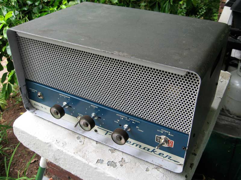

Bell Pacemaker 20:

This was an early mod. It wound up needing a replacement power transformer. I think I put some kind of deluxe hybrid circuit in there. I think it had two 6AV6 preamp tubes, one 12AX7 driver/phase inverter tube, and two 6V6 power tubes. There are volume, treble and bass controls. Mode switch that did something cool, I can't remember exactly what right now. 


Bogen J330:

I've done two of these. They make insanely great guitar amps. It has all octal socketed tubes, so I took a Bassman/Plexi type circuit and adapted it for 6SF5 preamp, 6SL7 driver, and coke bottle 6L6G tubes. One of my first paint experiments as well.


Precision Electronics (Grommes) Mixer:

This was originally a line level tube mixer so this one doesn't have a power section. It is essentially the preamp and tone stack from my version of the Bassman/Plexi with a two-band EQ. It also has an extra drive circuit. Stick it in front of even the cheesiest amp and have full tone!


 Bogen CHA-10:

This amp was ready for a champ-like treatment. At first I set up the 6AV6 and single ended 6L6 as a mostly stock power section. The interesting bit comes with the preamplifier stage. Originally I had the 6AU6 set up as a pentode, but the gain was just WAY too high, so I triode strapped it and all was well. Single volume control (microphone) and the tone control (phono) is just my favorite simple high end boost or cut. The tone switch is a mode control that implements or removes a negative feedback loop, taking the amp from tame to wild.


Newcomb Pathfinder 10:

This amp had a very odd stock circuit. It had a 6AU6 pentode and half of a 12AX7 acting together as a phase inverter. I got rid of all that weird stuff and installed a deluxe type circuit in here. Single input, gain control, and treble/bass controls. '10' watts of sweetness


Magnasync Moviola Squawk Box:

I installed essentially the Jekyll & Hyde amp circuit in this lovely little box. It was a beeitch trying to get the internal speaker to keep from rattling, but once I did this was a solid combo amp that had a surprising amount of power. I hooked it up to a full stack of 8x12" speakers once and it was plenty loud enough to keep up with a whole band. Not bad for a 6AQ5 single-ended power section!


Bogen CHB-10A:

Another donor with the Jekyll  & Hyde circuit. Though this one has a solid-state power supply and a 7868 power tube so it has a very different vibe. I've made 4 of these and they have all turned out amazing. So simple I think I could mod one from start to finish in less time than it takes to watch the original Star Wars trilogy. (That includes teardown, drilling, total rewire and recap, and basic testing!)


Stromberg-Carlson Mixer Model 38:

Another very early project for me. I think this was the last time I kept the original can caps installed. They worked great for a while, until one day when they failed and fried up the power transformer and nearly started a fire. I reworked it with a new transformer and all new caps. Lesson learned. The circuit was still pretty much stock. It had four mic inputs and one transformer balanced line output. Great tone with way too much gain! EQ section was subtle but cool. 

None of these beauties is still in my collection. They were all sold long ago to further the cause. I just thought I'd share some of the past to help show the evolution to the present. I have several similar amps awaiting mods for the station, so stay tuned.

Sunday, June 24, 2012

Signal Tracers as Recording Amps


Tablebeast Modified Heathkit IT-12 Signal Tracer:

I made a promise years ago to adopt a thread from an online forum regarding a Heathkit IT-12 Signal Tracer. I modified mine and never updated with details. From what I remember I had to sell it pretty quick, so it didn't stick around for long once it was finished. It was certainly cool though. With a 12AX7 as the preamp and driver tube, it doesn't really matter what power tube you're going into they all sound great. So, it won't be hard to apply basic 12AX7 guitar circuit ideas here. Plenty of designs of low watt amps will work here.

Here is the Heathkit IT-12 Stock Schematic, downloaded from vintage-radio.info http://www.vintage-radio.info/download/download.php?dir=heathkit&file=it-12.gif

Here is my modified schematic. It looks complete despite being a quick sketch:


Start out by removing entirely the external probe, C2, C3, and R14. R1, the 1 meg potentiometer will be replaced with a 500k Audio taper pot that will be placed between the first two stages. Replace probe jack with a 1/4" switching jack. Wire ground to the switch so it shorts out when nothing is plugged in. Wire a 68k resistor from the input jack to the grid of V1A. Replace R2 with a 1Meg resistor. The plate resistors are kind of small so we will replace R3 with a 220k and R5 with 100k.  You can keep the R4 bias resistor, but add a 25uf-25v electrolytic capacitor across it from cathode to ground. C4, the coupling cap should be replaced and increased to a .02uf film type. Install the new 500k pot after this cap. Replace the on/off knob for a tone pot. This tone pot will also be a 500k Audio type. Wire the wiper to the wiper of the volume pot, a 500pf cap from the first pin of the tone pot to the first pin of the volume pot (where it interfaces the new .02uf cap), and finally wire a .005uf cap from pin 3 of the tone pot to ground (the grounded pin 3 of the volume pot works perfectly). Then run a 1k resistor from where the wipers of the volume and tone pot meet to the grid of V1B. The old speaker switch will be the new power switch by the way.


V1B has a grid leak type bias setup with the cathode tied directly to ground. It is cheaper from a design point of view and was adequate for this type of circuit. For guitar amp use and for tone it is kind of a one trick pony, once it clips it gets gnarly really quick. There is little nuance, the nastiness is either on or off. I personally don't like this sound and when I find it in PAs or in test equipment I toss it in favor of a proper resistor bias. Plus adding a resistor here gives me the ability to add a feedback loop and feedback mode switch to give the amp two distinct tonal variations. My favorite size here would be 1.5k, though you could go lower like 820R or higher like 3k depending on what value you like best. 


Now the mode switch is where it gets a bit tricky. Leave this out if you don't want to bother. Use the old noise switch to perform this function. Run a feedback loop from the positive output of the speaker transformer secondary to a 27k resistor and connect that to the cathode of V1B. Wired in parallel with the bias resistor of V1B is a 47k resistor in series with a 25uf-25v electrolytic capacitor. The 47k resistor sits between the cathode of V1B and the + end of the electrolytic cap. The - end is grounded. Wired across the 47k resistor is a SPST switch that simply shorts out the 47k resistor. Essentially what this switch does is have the amp be cleaner and more linear with the switch open and the feedback loop engaged and more driven and non-linear/exaggerated with the switch closed. Closing the switch engages the bypass cap directly and effectively erases the feedback from the output transformer's feedback resistor.


The power section and Magic Eye meter section remains stock, but I will increase C7 to 100uf-25v and replace C9 with a film type .001uf cap. 


Adding to functionality I will add a switching 1/4" external speaker jack and padded 1/4" TRS headphone/line out jack with its own volume trim. First I will run a 100 ohm resistor across the transformer output as a minimum load even if a speaker cable is plugged in and there is no speaker hooked up. Then I run the + signal to the tip of the 1/4" jack. Wire the switch on that jack to the positive terminal on the built-in speaker. From the output transformer + terminal again run a 100 ohm resistor to pin 1 of the 1k Audio taper trim control. Pin 3 is grounded and pin 2 goes to two 100 ohm resistors that terminate at the two + lugs of a headphone line out jack. When using stereo headphones it provides mono signal to both phones or when using with an unbalanced TS 1/4" cable it shorts one of the signals to ground safely while the tip becomes your line out signal. You can send this padded signal to a recording device, power amp or the input of another instrument amplifier.


Heaters and power supply stay the same, but replace the caps with 50uf types of at least 200 volts. Install a panel mount 3AG fuse block of 1 amp slo-blo type fuse. Replace two prong AC connector with a 3 prong grounded IEC connector or hardwired three prong plug. Ground the ground wire to the chassis securely and run the Line signal to the fuse which is then in series with the power switch Wire the neutral AC leg directly to the power transformer primary.


I think that covers it. If I can help clarify anything please be sure to comment.

Saturday, June 23, 2012

Brute Force of Jekyll & Hyde


Guts of the Pre+Amp, TB-PPA1:

Here are the current audio circuits I am using in the Akai Pre+Amp and Ampex 601/602. First up is the Brute Force preamp circuit with optional XLR input and XLR dual output circuits. I use this circuit in the Pre+Amp and 2xPre units as well as in slightly tweaked form in the Ampex 601/602 Tape Machine Amps. Like the 2xPre Akai/Roberts monoblock mod, I can fit two channels in each 601 or 602 unit, the only difference between the two is the tube rectified/AC heaters in the 601 and solid state rectified/DC heaters in the 602.


If it is not clear, the first preamp stage's coupling cap connects to the switch of the 1/4" line in jack. V1 is a 6267/EF86 or you could use a 5879 which is basically the same tube with different pinout. The line amp is a 12AU7 type and you can use anything compatible you want here including 5963, my favorite. Also, the plate resistor on the top triode of the white cathode follower is 220R or 220 ohms. There are two outputs, one is transformerless at about 3k and impedance balanced while the other is 600 ohms transformer balanced. They can be used simultaneously. 


And then here is the Jekyll Hyde Amp. It has two distinct modes that give it two very different sounds. One tame and one wild, but both rich with tone. Some stuff might not be so easy to read. The cathode on the second 12AX7 stage has 27k feedback from the output transformer. At the cathode there is a 3k bias resistor and in parallel with a 47k resistor in series with a 25uf 50v cap. The mode switch effectively shorts the 47k resistor and erases the negative feedback. So: switch open is cleaner with NFB. Switch closed is wide open and driven with no feedback.

Circuit Design Philosophy


Self Taught Kiss:

I prefer to recreate things rather than perform simple tweaks, commit to outright restoring or even trying to reinvent the wheel. I like to take what is stock and, while keeping the spirit of it, rearrange varying amounts of what was already there. I do this to better suit an array of modern studio uses for a particular donor instead of its original intentions. So when I get a new donor amp that I haven't seen before I don't immediately try to shove a square peg in a round hole. Instead I look at what the donor has to offer and work from there. Since I always reuse the power transformer, that is the best place to start. Most of them aren't labeled, so I look up the tubes themselves and see what their respective heater and hi-pot voltage requirements are. Then I can reverse engineer at least what the minimum capabilities of the power transformer are. Most vintage iron was used in circuits that gave it plenty of headroom even beyond this minimal capability, but I try to keep whatever I replace the stock circuit with at or below the stock usage levels. If I have to goose it a bit, though I know this old stuff can take it. Once I have the voltage capabilities I look at the tube sockets themselves. Of course I can always swap out a 7 pin for a 9 pin or a 9 pin for an 8 pin octal, but sometimes it is best just to keep it simple and use what is there. Simple things like the stock socket types and layout often get my wheels spinning as I search out suitable circuits to place in my donor chassis. Once I have a general idea of what I want to put in there I consider controls and input/output. How many pots, switches, and jacks will I need to make my new circuit fully operational? What kind of space do I have or need to make in the chassis to fit what I need? Will there already be some extra functionality built into the stock unit that I can find a function for in the new circuit? At this point I will start to make changes to the new circuits. I like to add simple functions to my mods that are useful to modern recordists without making the new device overly complicated. I really strive to keep things simple and made the old ways. You'll never find anything frivolous in my units, though I do like to take advantage of slight tweaks that can greatly enhance the usefulness of a device. In the end the principle of K.I.S.S. or “Keep It Simple, Stupid” reigns supreme.

Thursday, June 21, 2012

Didn't You Used to Circuit-Bend?


Tablebeast Casio SK-1 model TB-SK01 mk II:

Yes, I did circuit-bend. And technically I still do from time to time. Though I only used the authentic, 'anti-theory' circuit-bent principles at the very beginning. Soon the whole anti-theory angle of it seemed somewhat lazy to me. I needed to know WHY such strange changes were happening and how those changes made such interesting sounds. I wanted to utilise theory to get the most out of this creative short circuiting called circuit-bending. At one point I even owned circuit-bent.com and ran a really lame website out of it. Back then when bending was so hip, I sold piles of stuff and never had time to even make a proper website! So even though I capitalized on the url, I've always considered what I am doing as modding instead of actual bending. I was never poking around blindly once I got to my third or fourth project. I started to figure out via message boards and my own research what was really going on. I was trying to get the most out of this digital phenomena of screwing up little bits of code to create such alien noises. Back in early 2001 when I first really got going with the bending I picked up my first Casio SK-1.

While plotting out the mods that I had found, I was becoming frustrated at how to tap into the vast wealth  available with this circuit. Up until that point I had been messing with Speak & Spells and other simple children's toys. A few switches, some body contacts, maybe a knob or two and they were ready to go! But this SK-1 was going to take a giant array of switches if it was going to do the SK-1's potential any justice. I thought instead to just breakout the points on the board to a series of contacts and then short them together with alligator clips. While I was doing this, trying to whittle down my favorite short circuit to like 24 switches or so, I realised that I could just install something similar to my clip setup, only more user friendly. My first idea was to use an external box with an umbilical cord attached. The box would have an array of 1/4" jacks. You could jump a cable from one socket to another, make a short circuit connection, and thus creating a patch for a modular bending mod! Immediately I was looking for something more streamlined. I didn't think the mod box was too elegant. I then stumbled on some RCA panels used for diy hi-fi. Since I needed a more compact setup I gave it a shot. There was actually enough room in the case itself if I yanked the speaker out, so I really liked how I could fit the mods all inside the keyboard and keep it as portable as stock. The kicker was that the RCA cables were a joy to play with. The way they contact the sockets allows you to do careful and nuanced shorting that was impossible with the 1/4" variety. Over the next few months I refined my design, changed the 8 point patch panels for some much nicer 12 pt panels that I found, and added some switches that shorted pair of sockets, so specific patches could be saved and engaged with a switch. The hybrid approach of full access to the live mod points and the programmable switches proved to be a popular combination. I soon outfitted this type of setup on nearly all my mods. After a while I figured out you could even patch back and forth with similar devices. The Yamaha DD drum machines, the Roland digital TR drum machines, the Casio SK samplers, could be CROSS PATCHED between devices with insane mods as a result. Needless to say others found this idea of modular bending via an RCA and later other types of patchbay was something they wanted to use for their own mods. Today they call an RCA patchbay of any sort a Tablebeast mod, especially when installed on an SK-1. I don't know if I am the first one to come up with using a patchbay to bend, but I sure was the one to popularise it. I sold a ton of SK-1s back in the day because of it! I don't sell many any more, but I offer them for sale as every time I try to quit selling my mkII SK-1 mod, folks wave money in my face so I help them out. What can I say? 11+ years later and I still love building them!

OK, so the point of all this circuit-bending talk and what it has to do with the xfmr page? I plan to build a few choice instruments for the studio and will for sure be using an MT-240 and SK-1 to help write sound FX for the podcast. Like I said, the main focus is tubes here, but there will be some synth, mod, and solid state projects added in for variety.

Wednesday, June 20, 2012

The Difference with My Mods


Akai / Roberts Monoblock Step by Step Conversion:

I have lot of folks reference other mods done to these Akai/Roberts monoblock Amps. Some folks add fancy transformers, remove feedback caps that open up the frequency response and lots of other little tweaks to the mostly stock units. Most of these folks leave the original wiring in place and even reuse the 50 year old capacitors. I don't do that. All my units are stripped down to bare parts, cleaned, refurbished and then reassembled from the ground up with ALL new wiring and electrolytic capacitors. I think of my amps as little hotrods. While most guys are rolling heaps out of garages and giving them a quickie tuneup, I am doing a ground up restoration and modification. Think of the wiring and caps like the old wiring, hoses, belts, gaskets, and tires on an old car. They are partly rubber and organic, just like the electrolytes in the filter capacitors. Would you drive a car on 50 year old tires and feel safe? They may work, but they will tend to fail on you at the WORST time. One this that bugs me with these tape machine donor amps is that they have a lot of circuitry devoted to tape functions. The energy and chassis space that is freed up from removing the erase circuit for example, give me an ability to add a line amp to the tweaked 6267 Preamp circuit. I reuse the super high quality dog bone resistors from the original amp, but again they have been taken apart gently, cleaned and reassembled with a minimum path, shielded cables, and a sophisticated ground system that minimizes hum and noise from the power supply. All stuff even the heaviest tweaked stock unit doesn't have! Look at the pics of the process from raw donor to skeleton, to fully rebuilt electronic sculpture. Here is a visual progression from donor to finished two unit. I did a whole run of six amps here. I prefer doing 4-6 a a time to combine steps and more efficiently build and troubleshoot. It takes me 3-4 weeks to finish all 6, doing about two a week. Each takes about 12-20 hours total time, so two of these make a nice chunk of my work week.